

1. Introduction
LED Wall-based virtual production enables virtual backgrounds to be rendered in real time and captured directly by a physical camera on set [1]. This approach allows virtual environments, physical lighting, and actors’ performances to be observed together during filming. Virtual production is a complex system that integrates LED walls, real-time rendering, camera tracking, and robotic camera control [2]. Despite these technical advances, camera operation still largely depends on the expertise of skilled human operators.
Previous studies on autonomous cinematography have mainly focused on virtual camera placement, camera trajectory generation, and camera movement planning [3, 4, 5, 6]. Drone and robotic camera studies have demonstrated the feasibility of automatic physical camera control [7, 8], but they generally assume a given real-world background and focus on controlling camera viewpoints or trajectories. Recent Large-Language Model (LLM)- and Vision-Language Model (VLM)-based film production studies have shown the potential of generating shot compositions, scene layouts, and camera settings from textual inputs [9, 10, 11]. However, relatively little attention has been given to an integrated system that connects script interpretation, camera tracking, robotic camera execution, and result observation within an actual LED Wall-based virtual production environment.
Meanwhile, translating the cinematic intention in a natural-language script into physical camera motion requires more than simply moving a camera. The system must interpret which subject is important in the script, identify and track the corresponding subject in the actual scene, and control the physical camera based on the intended shot and the subject’s motion. In this process, a gap remains between natural-language cinematic intent, the visual subjects in the scene, and executable camera control commands. To bridge this gap, LLMs and VLMs are useful because they can interpret the language instructions and connect them to visual evidence in images [12, 13].
Mascelli [14] insists that “every shot must serve the story” as a key principle of filmmaking. In this sense, camera shooting can be understood as a choice for narrative delivery. Bordwell and Thompson [15] explain that “a film employs cues in order to involve us.” They also distinguish a set of narrative elements which constitute the film’s story, from stylistic elements which includes how the camera moves. Based on this view, script-driven automatic camera control should be organized around the process of conveying narrative elements through cinematographic decisions: the system must interpret the intended subject and action from the script, ground them in the actual scene, execute camera movement to present them visually, and verify whether the resulting video makes them understandable.
In this paper, we propose a script-driven autonomous cinematography system for LED Wall-based virtual production. Given a natural-language script, the proposed system generates a structured shot plan that includes subject and camera movement. The shot plan serves as a system-level intermediate representation shared by the subject selection, visual tracking, and robotic camera control modules. Based on this representation, the system selects the target subject in the camera image, tracks it over time, and converts the tracking results into pan, tilt, and linear motion commands for robotic camera execution in a virtual production environment. After execution, the resulting video is analyzed to verify whether it sufficiently reflects the script’s intention, and the shot plan is updated if it does not. We implement the proposed system using an LED Wall, a game engine, camera tracking, and a robotic camera system to demonstrate this system-level feasibility.
The main contributions of this system are as follows. First, we propose a script-driven autonomous camera control system that connects shot plan generation, subject selection, tracking, robotic camera control, and post-execution result observation in an LED Wall-based virtual production environment. Second, we use a structured shot plan as an executable interface that connects script-level cinematic intent with target subject selection, tracking, and robotic camera control and shot plan revision. Third, we demonstrate the feasibility of the proposed system in an actual virtual production environment consisting of an LED Wall, Unreal Engine, camera tracking, and a robotic camera system.
2. Related Works
Virtual production has evolved from chroma-key-based compositing [16] and simulcam [1] workflows toward LED Wall-based in-camera VFX. In LED Wall-based virtual production, virtual backgrounds rendered by a real-time game engine are displayed on LED panels and captured directly by a physical camera. This allows the actor, lighting, and virtual environment to be integrated during filming, while the camera pose is tracked and reflected in the virtual scene [17, 18]. Therefore, an LED Wall-based virtual production stage should be regarded as a physical production system that integrates LED Wall configuration, camera tracking, multi-display synchronization, and camera operation.
Although virtual production technologies have improved production efficiency and visual consistency [19, 20], camera operation in such environments still requires skilled human operators. For small teams or non-expert users, controlling the camera while also managing virtual production-specific components remains difficult. Therefore, camera automation in virtual production requires a system-level approach that connects cinematic intent, physical camera tracking, robotic camera control, and the virtual production rendering environment.
Classical cinematography literature defines camera placement, shot size, framing, and camera movement as important elements for conveying visual and narrative intention [21]. Based on these principles, autonomous cinematography has been studied in virtual cinematography, and robotic camera control. Early work on virtual camera control formulated camera control as a problem of computing camera parameters, viewpoints, or movements that satisfy user-specified visual or narrative constraints [22, 23]. Subsequent studies introduced camera representations and control methods such as toric space [4], example-driven virtual cinematography [5], and camera keyframing with style and control [6]. These approaches contributed to generating plausible camera placements, trajectories, and camera motions in virtual environments.
Another line of work has explored physical camera automation in drone and robotic camera systems. Drone cinematography studies have planned camera paths that follow a subject while satisfying cinematographic constraints such as shot size, composition, and visibility [7, 24]. Other robotic camera systems have used visual feedback or user-provided references to adjust physical camera viewpoints and improve image composition [25, 26].
These studies show that camera placement and trajectory generation can be automated under predefined visual objectives. However, most prior work assumes that the target subject and the desired camera behavior are already given and primarily focuses on generating viewpoints or trajectories. In contrast, we start from a natural-language script, infer the target subject and camera movement, and convert them into a structured shot plan for physical camera execution.
Recent advances in LLMs have enabled text-based planning and script interpretation for film and video production. Prior studies such as VideoDirectorGPT [10], and Anim-Director [11] use LLMs to decompose textual inputs into scene layout, visual composition, and cinematographic instructions. FilmAgent [9] further shows that LLM-based agents can generate cinematography-related plans in a virtual filmmaking environment. Our preliminary study also explored script-driven camera automation in a physical virtual production setup by converting natural-language scripts into structured shot plans and executing them through a robotic camera system [27]. However, these approaches primarily focus on generating or executing camera plans and offer limited mechanisms for verifying execution results and revising the shot plan when the initial plan does not adequately present the intended subject or action.
3. Proposed System
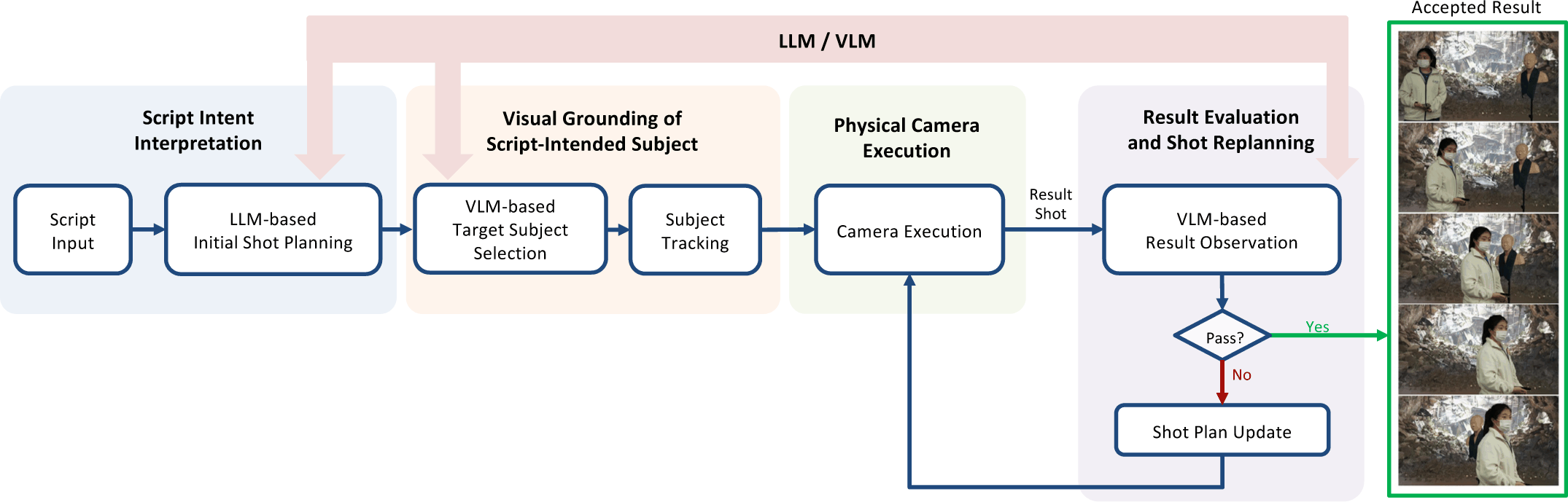
Fig. 1 shows the overall pipeline of the proposed script-driven camera automation system for virtual production. The system connects natural-language script understanding to physical camera execution through shot planning, target subject selection, visual tracking, robotic camera control, and executed-video observation. Given a script, the system generates a structured shot plan and uses it as the main interface for target subject selection, visual tracking, and robotic camera control. Through this pipeline, script-level cinematic intent is translated into executable camera behavior, including which subject to film, how to track the subject, and how the robotic camera should move during the shot. The physical virtual production setup that supports this pipeline, including LED Wall rendering, camera tracking, synchronization, and robotic camera motion, is described in the next section.
The proposed system was implemented in an LED Wall-based virtual production environment. Camera automation in this environment requires the physical camera pose to be consistently connected with the Unreal Engine virtual camera, the LED Wall output, the tracking coordinate system, and the robotic camera motion. Therefore, the setup was organized into separate components for rendering, tracking, synchronization, and robotic control. As shown in Fig. 2, the setup consists of an LED Wall, a master node, two nDisplay render nodes, LED processors, Vive Mars1 camera tracking, and a robotic camera system. The master node handles the overall pipeline and camera control, while the render nodes drive separate LED Wall regions and are synchronized using framelock to reduce frame mismatch and screen tearing.
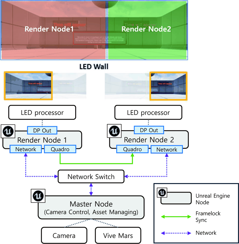
The LED Wall was configured as an extended virtual background by arranging two 3840×2160 LED Wall regions side by side as shown in Fig. 2. Each LED Wall supports a 1.5 mm pixel pitch and a maximum refresh rate of 60 Hz, which helps reduce moiré and flicker during filming. The virtual background rendered in Unreal Engine is divided into an inner frustum and an outer frustum, as shown in Fig. 3. The inner frustum corresponds to the physical camera view and is updated in real time based on the tracked camera pose. The outer frustum fills the surrounding LED Wall area at a lower rendering priority, helping preserve environmental lighting and spatial context around the camera view.
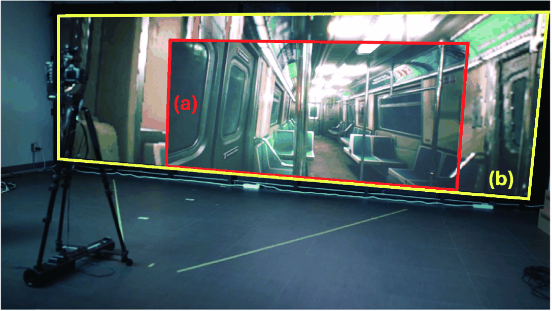
As shown in Fig. 2, we used Unreal Engine nDisplay with a multi-node cluster rendering configuration to stably drive the high-resolution LED Wall. The cluster consisted of one master node and two render nodes. The master node handled session management and input control, while the two render nodes separately rendered the left and right regions of the LED Wall. Both render nodes used the same NVIDIA RTX 6000 Ada GPU to maintain consistent rendering performance. This configuration was designed to render the camera-dependent inner frustum with high resolution. The camera position and orientation measured by the Vive tracker were received through LiveLink2, and the inner frustum was updated every frame accordingly. In addition, a Quadro Sync II-based framelock was applied so that each render node output the LED Wall image at the same frame timing, reducing frame mismatches and screen tearing between nodes. The outer frustum surrounding the inner frustum as shown in Fig. 3 was rendered at a relatively lower resolution to fill the remaining LED Wall area and maintain ambient lighting and spatial context in the filming space.
For camera tracking, we used a Vive Mars-based tracking system to transmit the position and rotation of the physical camera to Unreal Engine in real time. A Vive tracker was attached to the camera rig, and two base stations were installed to ensure stable tracker recognition. The tracking data were sent to Unreal Engine through LiveLink and applied to the virtual camera. As the physical camera moves, the virtual camera pose and the inner frustum are updated every frame to keep the virtual background on the LED Wall aligned with the physical camera viewpoint.
Accurate virtual production shooting required consistent alignment among the coordinate systems of the physical camera, tracker, LED Wall, and Unreal Engine scene. Since the tracker was mounted above the camera body, we calibrated the fixed offset between the tracker’s reference point and the camera’s optical center. The center of the LED Wall floor was then set as the reference point for the tracking space and aligned with the nDisplay root coordinate system. After that, the reference anchor, tracker object, and virtual camera were arranged in a parent-child hierarchy.
Through this configuration, the position and rotation of the physical camera were transferred into the nDisplay coordinate system, allowing the physical camera movement and the Unreal Engine virtual camera movement to maintain the same viewpoint relationship. The field of view of the physical camera lens and the stage layout information were also reflected in the Unreal Engine settings to ensure spatial consistency between the virtual background and the captured image.
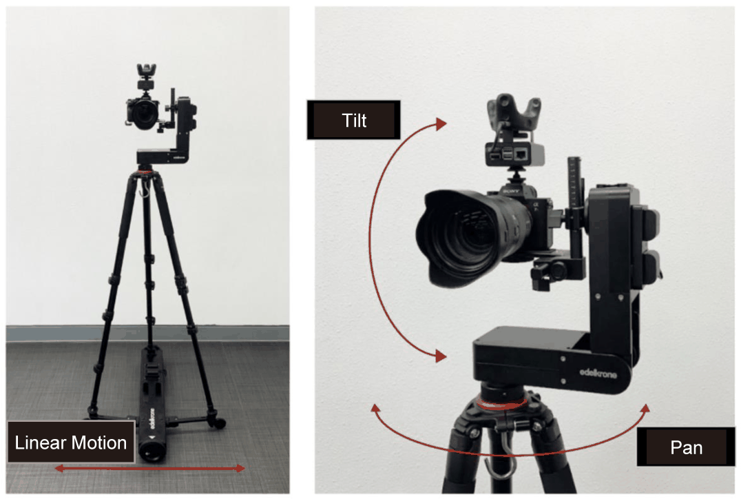
The robotic camera is shown in Fig. 4. We used an Edelkrone motion control system3 that supports pan, tilt, and linear motion. The system receives wireless commands via an HTTP-based control protocol, and the proposed system sends Python commands to control each motion axis in real time. The pan and tilt axes are used to adjust the subject position within the frame, while the linear motion axis is used to reproduce planned camera movements and adjust the camera-subject distance. The motion speed and easing parameters of each axis were empirically adjusted to obtain smoother camera movement in the physical filming environment.
The first stage in Fig. 1 converts a natural-language script into a structured shot plan. Before shot planning, the language model is initialized with a planning prompt that includes cinematography domain knowledge, predefined shot-plan fields, allowed camera movement categories, output-format instructions, and example input-output pairs. In the current implementation, the shot plan consists of two fields: subject and camera_movement.
The purpose of this stage is to convert the script into an executable representation that can be directly used by the following modules. The subject selection module uses the subject field to identify the target in the image and initialize the tracking subject. The camera control module uses the camera_movement field to determine the robotic camera motion mode.
The subject field is represented as a natural-language description of the target subject, such as A woman, the person wearing earphones, or Person B. This field is used as a query for selecting the target subject in the initial camera frame. The camera movement field is selected from the camera movement candidates: static, track, dolly_in, dolly_out, truck_left, and truck_right. These candidates are defined based on the controllable motion axes of the robotic camera system. The shot-planning stage outputs a JSON-formatted shot plan, such as {"subject": "A woman", "camera movement": "track"}. During post-execution replanning, only the subject field or the camera movement field is revised based on the observed failure evidence, and the updated shot plan is re-executed.
The visual grounding stage in Fig. 1 connects the subject described in the shot plan with the corresponding visual subject in the camera image. The subject field is extracted from the shot plan and used as a text query for target subject selection. This stage is necessary because the script-level subject description, such as A woman or the person wearing earphones, does not directly indicate which visual subject in the camera image should be tracked.
In the current implementation, the system first captures the initial camera frame and detects human candidates using YOLO [28]. Each detected candidate is assigned a target ID, and the initial frame is annotated with the candidate bounding boxes and target IDs. The VLM receives the annotated frame and the subject field from the shot plan, and outputs the target ID that best matches the script-intended subject.
The selected target ID is used as the tracking target in the YOLO and DeepSORT [29] tracking module. During camera execution, the tracker follows the selected subject and provides the target bounding box for camera control. If the selected subject is found to be inconsistent with the script intention through post-execution observation, the subject field can be revised during shot replanning and the target subject can be selected again in the next attempt.
The camera control stage in Fig. 1 executes the camera movement specified in the shot plan using the tracking result and the robotic camera system. During execution, the system tracks the selected subject using YOLO and DeepSORT and obtains the target bounding box for each frame. The control policy depends on the camera_movement field in the shot plan.
For track, the system uses the center error between the target subject’s bounding box and the image frame to keep the target subject near the center of the frame. Let (xc, yc) denote the center of the target subject’s bounding box, and let W and H denote the frame width and height. The horizontal and vertical errors are computed as
The pan axis is controlled using the horizontal error ex, while the tilt axis is controlled using the vertical error ey.
For dolly_in and dolly_out, the system controls the linear motion axis based on the subject size in the frame. In the current implementation, shot-size adjustment is defined between full shot and medium shot. The face bounding box size is used to estimate whether the subject is closer to the target shot size. The camera moves forward for dolly_in and backward for dolly_out until the target shot-size condition is reached. In the current setup, the linear motion axis is configured for one direction per execution. Therefore, dolly_in/dolly_out and truck_left/truck_right are treated as separate linear-motion modes and are not executed simultaneously.
For static, all motion axes are set to zero velocity, and the camera remains fixed. For truck_left and truck_right, the robotic camera moves along the linear axis with a predefined speed in the left or right direction. These movements do not use tracking-based speed adjustment in the current implementation.
The resulting velocity commands are sent to the robotic camera system through the HTTP-based command interface, while the tracked physical camera pose is reflected in the Unreal Engine camera actor and the LED Wall inner frustum.
After camera execution, the recorded result video is observed to verify whether the script intention is visually presented in the executed shot. As shown in Fig. 5, this stage consists of three steps: scene description, result evaluation, and shot replanning.
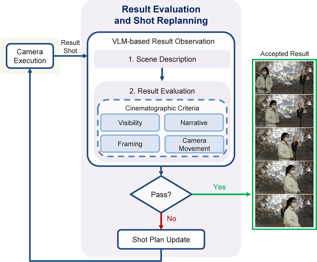
In the scene description step, the VLM receives sampled frames from the executed video and describes the visual result in a structured dictionary format. The description is organized into four categories: visibility, framing, narrative emphasis, and camera movement. These perspectives are organized based on prior discussions in cinematography and autonomous cinematography [30, 15]. The visibility field describes which subjects and actions are visible in the scene. The framing field describes where the subject is located in the frame and how the subject moves over time. The narrative emphasis field describes which subject is visually dominant and why it appears dominant. The camera movement field describes how the target subject appears over time and whether the camera motion maintains the subject and action within the frame.
This process follows a VQA-style evaluation [31], where the VLM answers whether the executed video satisfies each cinematographic criterion based on the sampled frames. In the result evaluation step, the VLM receives the script, the current shot plan, sampled frames, and the scene description. The output is a structured pass/fail result for four cinematographic criteria: visibility, framing, narrative emphasis, and camera movement. Visibility checks whether the main subject and action described in the script are visible. Framing checks whether the main subject and action are appropriately positioned within the frame. Narrative emphasis checks whether the visually dominant subject corresponds to the script-relevant target. Camera movement checks whether the camera motion maintains the visibility of the main subject and action over time. The shot is accepted only when all four criteria are evaluated as successful.
If any criterion fails, the system performs VLM-based shot replanning. The VLM receives the script, the current shot plan, the scene description, the result evaluation, and the attempt history, which includes previous shot plans and reasoning results. To isolate the effect of each revision, only one major field is updated in each attempt: either subject or camera_movement. The revised subject is represented as a natural-language target description, while the revised camera_movement is selected from the predefined camera movement candidate set. The updated shot plan is then passed back to the execution stage for the next attempt. The maximum number of attempts is set to five.
4. Experiments
Experiments were conducted using the LED Wall-based virtual production system described in Section 3.2. The setup included a Sony A7R IV camera, Vive Mars CamTrack, Unreal Engine with nDisplay, and an Edelkrone robotic camera system supporting linear translation, pan, and tilt. GPT-4.14 was used as the language and vision-language model for shot planning, subject selection, executed-video observation, result evaluation, and shot replanning.
The experiments used two virtual backgrounds: a cave5 and a subway train6. The cave scene contained a relatively large number of detailed background objects, with an asset size of approximately 17GB, whereas the subway train scene was lighter, with approximately 800MB asset size. The LED Wall output was configured at 7680 × 2160 resolution through nDisplay. During the experiments, the rendering frame time was observed to be approximately 16.7ms per frame, corresponding to the target 60 fps output.
We used three shot-level test scripts that describe a target subject, subject action, and, when specified, an intended camera movement. These scripts were used to examine whether the system can connect script-level intent to physical camera execution and result-based shot replanning in the virtual production setup.
We tested the system using three script-based demonstration scenarios. Since the goal of this study is to verify whether script-level intent can be connected to physical camera execution and result-based shot replanning in an actual virtual production system, we used shot-level scripts rather than long multi-shot sequences. Script 1 and Script 2 were designed to examine whether the system can execute planned camera movements from natural-language scripts, while Script 3 was designed to examine whether the executed video can be used for shot replanning when the initial result does not sufficiently maintain the intended subject.
The first scenario uses the script, “The person is still standing. His/her expression turns serious. Camera Dolly in.” This script explicitly describes both the target subject’s action and the intended camera movement. From this script, the system generates a shot plan with the target subject and dolly_in movement. As shown in Fig. 6, the camera moves closer to the subject over time, and the subject is progressively framed in a tighter shot.

The second scenario uses the script, “A person walks into the cave. Camera track.” This script describes the target subject’s action and specifies a tracking movement. From this script, the system generates a shot plan with the target subject and track movement. As shown in Fig. 7, the camera follows the subject as the subject walks into the cave scene, and the subject remains visible across the captured frames.

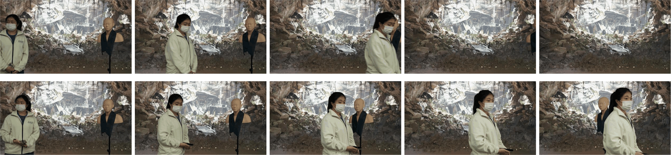
The third scenario uses the script, “Person B walks past A and heads forward.” This script describes the intended action at an abstract level, but the visual identity of Person B must be grounded in the actual scene. From this script, the system generates an initial shot plan and executes the planned camera movement. As shown in the top row of Fig. 8, the initial execution does not sufficiently maintain the intended subject within the frame. The executed video is used for result evaluation and shot replanning. The revised shot plan is executed again, and the final result, shown in the bottom row of Fig. 8, presents the intended subject and action more clearly.
We evaluate whether the system conveys the script-level intention through the generated shot plan and the executed video.
The evaluation considers whether the intended subject and camera movement are presented in accordance with the four cinematographic criteria used in the result evaluation stage: visibility, framing, narrative emphasis, and camera movement. A result is considered successful only when all four criteria are satisfied.
For Scripts 1 and 2, the generated shot plans correctly select the intended subject and the camera movement specified in the scripts. In Script 1, the planned dolly_in movement is visually reflected as the camera moves closer to the subject over time and produces a tighter shot, as shown in Fig. 6. In Script 2, the planned track movement keeps the intended subject visible within the frame, as shown in Fig. 7. Therefore, both results satisfy all four criteria, as shown in Table 1.
| Script # | Vis. | Fram. | Narr. | Cam Move. |
|---|---|---|---|---|
| 1 (Initial) | Succ. | Succ. | Succ. | Succ. |
| 2 (Initial) | Succ. | Succ. | Succ. | Succ. |
| 3 (Initial) | Succ. | Fail | Succ. | Fail |
| 3 (Replanned) | Succ. | Succ. | Succ. | Succ. |
For Script 3, the initial execution fails to maintain the intended subject within the frame. As shown in the top row of Fig. 8, the subject moves out of the frame over time. The VLM-based result observation stage reports a framing failure because the intended subject is partially cut off on the right side of the frame, and a camera movement failure because the camera does not follow the intended subject as shown in Table 1. Based on this failure evidence, the system revises the shot plan and re-executes the shot. After replanning, the final execution maintains the intended subject and action more stably within the frame, as shown in the bottom row of Fig. 8. Table 1 shows that the result satisfies all four criteria.
As shown in Table 2, we evaluate target visibility and framing stability in the executed results. Script 1 and Script 2 achieve high target-in-frame ratios in the initial shot plans, indicating that the target subjects remain visible within the frame. They also show low mean center errors, indicating that the target bounding box centers are maintained close to the frame center. In Script 3, the final shot plan executed after the replanning loop achieves a higher target-in-frame ratio than the initial shot plan. It also reduces the mean center error, indicating that the target bounding box center is maintained closer to the frame center. The mean center error was normalized by dividing the distance between the target bounding box center and the frame center by the maximum center-to-corner distance in a 1920 × 1080 frame.
| Script # | Target-in-frame ratio | Mean center error |
|---|---|---|
| 1(Initial) | 1.00 | 0.05 |
| 2(Initial) | 1.00 | 0.27 |
| 3(Initial) | 0.63 | 0.58 |
| 3(Replanned) | 1.00 | 0.34 |
These results show that the proposed system generally maintains the target subject visible and close to the frame center in successful executions. In particular, the improvement in Script 3 after replanning indicates that the planning loop helps recover target visibility and framing stability when the initial execution fails.
5. Conclusion and Future Work
In this paper, we propose a VLM-based script-driven camera automation system for LED Wall-based virtual production. The proposed system connects natural-language script understanding to physical camera execution by generating a structured shot plan, visually grounding the target subject in the camera image, tracking the subject, and controlling a robotic camera system according to the planned camera movement. In addition, the system observes the executed video, evaluates whether the intended subject and action are visually understandable, and updates the shot plan when the result does not sufficiently reflect the script’s intention.
The current system still has several limitations. First, the robustness of the proposed pipeline should be further evaluated across more diverse scripts, visual scenes, subject configurations, and camera movements. Second, the current demonstrations are limited to short shot-level scenarios. Future work will extend the system toward long-horizon multi-shot filming, where multiple subjects, actions, and camera movements must be planned and executed sequentially. In addition, we plan to further develop and evaluate the feedback process so that the system can more reliably verify execution results, identify failure cases, and revise the shot plan for subsequent camera execution.